README
hdl-js

![]()

Hardware description language (HDL) parser, and Hardware simulator.
Table of Contents
- Installation
- Development
- Usage as a CLI
- Usage from Node
- Parser
- Emulator
- Online tool
- Built-in gates
- Viewing gate specification
- Specifying output format
- Columns whitelist
- Testing gates on passed data
- Pins
- Creating gates from default spec
- Exec on set of data
- Validating passed data on gate logic
- Data files for execution
- Gates scripting
- Sequential run
- Gate events
- Main chip groups
- Clock
- Composite gates
- Code generator
Installation
The hdl-js tool can be installed as an npm module:
npm install -g hdl-js

hdl-js --help
Development
- Fork https://github.com/DmitrySoshnikov/hdl-js repo
- If there is an actual issue from the issues list you'd like to work on, feel free to assign it yourself, or comment on it to avoid collisions (open a new issue if needed)
- Make your changes
- Make sure
npm teststill passes (add new tests if needed) - Submit a PR
For development from the github repository, run build command to generate the parser module, and transpile JS code:
git clone https://github.com/<your-github-account>/hdl-js.git
cd hdl-js
npm install
npm run build

./bin/hdl-js --help
NOTE: JS code transpilation is used to support older versions of Node. For faster development cycle you can use npm run watch command, which continuously transpiles JS code.
Usage as a CLI
Check the options available from CLI:
hdl-js --help
Usage: hdl-js [options]

Options:
  --help, -h          Show help                                        [boolean]
  --version, -v       Show version number                              [boolean]
  --gate, -g          Name of a built-in gate or path to an HDL file
  --parse, -p         Parse the HDL file, and print AST
  --list, -l          List supported built-in gates
  --describe, -d      Prints gate's specification
  --exec-on-data, -e  Evaluates gate's logic on passed data; validates outputs
                      if passed
  --format, -f        Values format (binary, hexadecimal, decimal)
                                                  [choices: "bin", "hex", "dec"]
  --run, -r           Runs sequentially the rows from --exec-on-data table
  --clock-rate        Rate (number of cycles per second) for the System clock
  --columns, -c       Whitelist of columns (comma-separated) to show in the
                      table
  --script, -s        Run testing script, which automatically loads a gate,
                      tests the logic, and compares the results.
NOTE: the implementation of some built-in chips, and the HDL format is heavily inspired by the wonderful nand2tetris course by Noam Nisan and Shimon Schocken.
Example of a CLI command to describe Xor gate:
hdl-js --gate Xor --describe

"Xor" gate:

Description:

  Implements bitwise 1-bit Xor ^ operation.

...
Usage from Node
The tool can also be used as a Node module:
const hdl = require('hdl-js');

// Check the API:
console.log(hdl);
The hdl-js exposes the following API:
parse(hdl: string)-- parses an HDL code; convenient facade method forparser.parseparseFile(fileName: string)-- parses an HDL file; facade forparser.parseFilefromHDLFile(fileName: string)-- loads a gate class defined in an HDL file; facade forHDLClassFactory.fromHDLFilefromHDL(hdl: string)-- creates a gate class according to passed HDL spec; facade forHDLClassFactory.fromHDL- parser -- the parser module exposed
- emulator -- hardware emulator, which includes:
Pin- a pin "wire" used to patch inputs and outputs of a gateBuiltInGate-- base class for all built-in gatesCompositeGate-- base class used for user-defined gates from HDL; see Composite gates sectionHDLClassFactory-- class loader for gates defined in HDL- ScriptInterpreter -- execution engine for test scripts
- Clock -- class to manage clocked gates. Contains:
SystemClock-- main System clock used to synchronize all gated chips
BuiltInGates-- map of all built-in gates:AndOr- ...
generateFromAST(ast)-- generates an HDL code from AST; convenient facade forgenerator.fromASTgenerateFromCompositeGate(gate)-- generates an HDL code from a composite gate instance; convenient facade forgenerator.fromCompositeGate- generator -- the generator module exposed
Parser
The hdl-js is implemented as an automatic LR parser using Syntax tool. The parser module is generated from the corresponding grammar file.
Format of an HDL file
A hardware chip is described via the CHIP declaration, followed by a chip name, and a set of sections:
CHIP <chip-name> {
  <section>
  <section>
  ...
}
The sections include:
IN-- inputs of a gateOUT-- outputs of a gatePARTS-- the actual implementation body of a chip, composed from other chipsBUILTIN-- refer to a name of a built-in chip: in this case the implementation is fully take from the built-in gate, and thePARTSsection can be omittedCLOCKED-- describes which inputs/outputs are clocked
Let's take a look at the examples/And.hdl file:
/**
 * And gate:
 * out = 1 if (a == 1 and b == 1)
 *       0 otherwise
 */

CHIP And {
  IN a, b;
  OUT out;

  PARTS:

  Nand(a=a, b=b, out=n);
  Nand(a=n, b=n, out=out);
}
Once we have an HDL file, we can feed it to the parser, and get its AST.
Parsing a file to AST
The parser can be used from CLI, and from Node.
Taking the examples/And.hdl file from above, and running the:
./bin/hdl-js --gate examples/And.hdl --parse
We get the following AST (abstract syntax tree):
{
  type: 'Chip',
  name: 'And',
  inputs: [
    {
      type: 'Name',
      value: 'a'
    },
    {
      type: 'Name',
      value: 'b'
    }
  ],
  outputs: [
    {
      type: 'Name',
      value: 'out'
    }
  ],
  parts: [
    {
      type: 'ChipCall',
      name: 'Nand',
      arguments: [
        {
          type: 'Argument',
          name: {
            type: 'Name',
            value: 'a'
          },
          value: {
            type: 'Name',
            value: 'a'
          }
        },
        {
          type: 'Argument',
          name: {
            type: 'Name',
            value: 'b'
          },
          value: {
            type: 'Name',
            value: 'b'
          }
        },
        {
          type: 'Argument',
          name: {
            type: 'Name',
            value: 'out'
          },
          value: {
            type: 'Name',
            value: 'n'
          }
        }
      ]
    },
    {
      type: 'ChipCall',
      name: 'Nand',
      arguments: [
        {
          type: 'Argument',
          name: {
            type: 'Name',
            value: 'a'
          },
          value: {
            type: 'Name',
            value: 'n'
          }
        },
        {
          type: 'Argument',
          name: {
            type: 'Name',
            value: 'b'
          },
          value: {
            type: 'Name',
            value: 'n'
          }
        },
        {
          type: 'Argument',
          name: {
            type: 'Name',
            value: 'out'
          },
          value: {
            type: 'Name',
            value: 'out'
          }
        }
      ]
    }
  ],
  builtins: [],
  clocked: [],
}
The parse command is also available from Node:
const fs = require('fs');
const hdl = require('hdl-js');

const hdlCode = fs.readFileSync('./examples/And.hdl', 'utf-8');

console.log(hdl.parse(hdlCode)); // HDL AST
There is also convenient parseFile method:
const hdl = require('hdl-js');

console.log(hdl.parseFile('./examples/And.hdl')); // AST
AST nodes specification
The AST format of the HDL is currently simple, and includes the following node types:
Chip AST node
This is the top-level "Chip" node, and has the following properties:
{
  type: 'Chip',

  /**
   * List of inputs pins.
   */
  inputs: [Name, ...],

  /**
   * List of output pins.
   */
  outputs: [Name, ...],

  /**
   * Gate implementation list.
   */
  parts: [ChipCall, ...],

  /**
   * If present, contains the names of the built-in chips used in this gate.
   */
  builtins: [Name, ...],

  /**
   * If present, shows the list of clocked inputs/outputs.
   */
  clocked: [Name, ...],
}
Name AST node
The Name type is used to define the names of the input/output pins, names of the arguments in ChipCall, etc. The node has the following properties:
{
  type: 'Name',

  /*
   * The actual name of a pin.
   *
   * Example: `IN a;`, the `value` is `a`.
   */
  value: string,

  /**
   * The `size` is only available in the input/output names.
   *
   * Example: `IN a[16];`, the `size` is 16.
   */
  size?: number,

  /**
   * An index of a particular bit. The `index` property is
   * only available in the arguments of a `ChipCall`.
   *
   * Example: `And(a=a[4], ...)`, the `index` is 4 here.
   */
  index?: number,

  /**
   * A range of the bits. The `range` property is
   * only available in arguments of a `ChipCall`/
   *
   * Example: `Mux4Way16(..., sel=address[0..11])`,
   * the range (inclusive) here is `0..11`.
   */
  range?: {
    from: number,
    to: number,
  },
}
ChipCall AST node
The ChipCall can appear only in the parts section of the 'Chip' node. This is an evaluation call to an internal chip, used in implementation of this gate.
It has the following properties:
{
  type: 'ChipCall',

  /**
   * The name of the internal chip, which is being called.
   */
  name: string,

  /**
   * The list of arguments to the call. The values in each argument
   * correspond to the inputs/outputs specification of a gate.
   */
  arguments: [Argument, ...]
}
Argument AST node
Arguments appear as parts of the ChipCall node types. An argument has the following properties:
{
  type: 'Argument',

  /**
   * The name of the argument.
   */
  name: Name,

  /**
   * The value of the argument.
   */
  value: Constant | Name,
}
Constant AST node
Constants can be used as input values for pins. These are numbers, and two special names, false, and true, which correspond respectively to 0, and 1 values.
{
  type: 'Constant',

  /**
   * The number value of the constant.
   */
  value: NUMBER,

  /**
   * The value as it appears in the source code.
   */
  raw: 'true' | 'false' | NUMBER
}
Emulator
Hardware emulator module simulates and tests logic gates and chips implemented in the HDL, and also provides canonical implementation of the built-in chips.
Online tool
The emulator module is exposed as a UI tool, where you can design chips in HDL, introspect built-in gates, and check the results of gates evaluation.
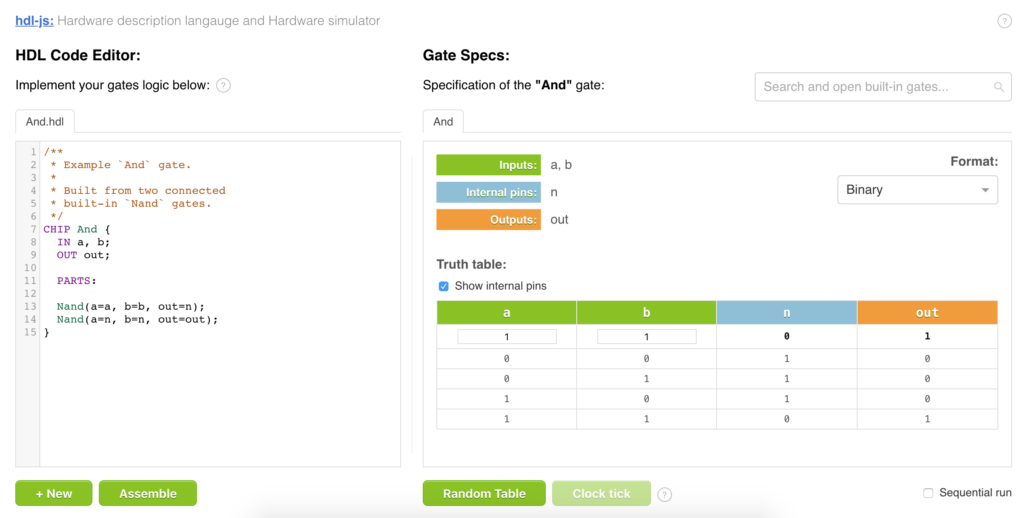
Built-in gates
In general, all the gates can be built manually in HDL from the very basic Nand or Nor gates. However, hdl-js also provides implementation of most of the computer chips, built directly in JavaScript.
You can use these gates as building blocks with a guaranteed faster implementation, and also to check your own implementation, in case you build a custom version of a particular basic chip.
The --list (-l) command shows all the built-in gates available in the emulator. The gates can be analyzed, executed, and used further as basic building blocks in construction of compound gates.
./bin/hdl-js --list

Built-in gates:

- And
- And16
- Or
- ...
Once you know a gate of interest, you can introspect its specification.
Viewing gate specification
To see the specification of a particular gate, we can use --describe (-d) option, passing the name of a needed --gate (-g):
./bin/hdl-js --gate And --describe
Result:
"And" gate:

Description:

  Implements bitwise 1-bit And & operation.

Inputs:

  - a
  - b

Outputs:

  - out

Truth table:

┌───┬───┬─────┐
│ a │ b │ out │
├───┼───┼─────┤
│ 0 │ 0 │  0  │
├───┼───┼─────┤
│ 0 │ 1 │  0  │
├───┼───┼─────┤
│ 1 │ 0 │  0  │
├───┼───┼─────┤
│ 1 │ 1 │  1  │
└───┴───┴─────┘
NOTE: the
--gateoption handles both, built-in gates by name, and custom gates from HDL files.
From Node the specification of a built-in gate is exposed via Spec option on the gate class:
const hdl = require('hdl-js');

const {And} = hdl.emulator.BuiltInGates;

console.log(And.Spec);

/*

Output:

{
  description: 'Implements bitwise 1-bit And & operation.',

  inputPins: ['a', 'b'],

  outputPins: ['out'],

  truthTable: [
    {a: 0, b: 0, out: 0},
    {a: 0, b: 1, out: 0},
    {a: 1, b: 0, out: 0},
    {a: 1, b: 1, out: 1},
  ]
}

*/
Specifying output format
Using --format option it is possible to control the format of the input/output values. For example, the truth table of the And16 gate in binary (default), and hexadecimal formats:
./bin/hdl-js --gate And16 --describe
Binary output format:
┌──────────────────┬──────────────────┬──────────────────┐
│      a[16]       │      b[16]       │     out[16]      │
├──────────────────┼──────────────────┼──────────────────┤
│ 0000000000000000 │ 0000000000000000 │ 0000000000000000 │
├──────────────────┼──────────────────┼──────────────────┤
│ 0000000000000000 │ 1111111111111111 │ 0000000000000000 │
├──────────────────┼──────────────────┼──────────────────┤
│ 1111111111111111 │ 1111111111111111 │ 1111111111111111 │
├──────────────────┼──────────────────┼──────────────────┤
│ 1010101010101010 │ 0101010101010101 │ 0000000000000000 │
├──────────────────┼──────────────────┼──────────────────┤
│ 0011110011000011 │ 0000111111110000 │ 0000110011000000 │
├──────────────────┼──────────────────┼──────────────────┤
│ 0001001000110100 │ 1001100001110110 │ 0001000000110100 │
└──────────────────┴──────────────────┴──────────────────┘
With --format hex:
./bin/hdl-js --gate And16 --describe --format hex
Hexadecimal output format:
┌───────┬───────┬─────────┐
│ a[16] │ b[16] │ out[16] │
├───────┼───────┼─────────┤
│ 0000  │ 0000  │  0000   │
├───────┼───────┼─────────┤
│ 0000  │ FFFF  │  0000   │
├───────┼───────┼─────────┤
│ FFFF  │ FFFF  │  FFFF   │
├───────┼───────┼─────────┤
│ AAAA  │ 5555  │  0000   │
├───────┼───────┼─────────┤
│ 3CC3  │ 0FF0  │  0CC0   │
├───────┼───────┼─────────┤
│ 1234  │ 9876  │  1034   │
└───────┴───────┴─────────┘
Columns whitelist
Using the --columns (-c) option it is possible to specify a whitelist of columns which should be printed.
For example, the resulting list of columns of the examples/MipsAlu16.hdl gate is quite large, and shows a lot of internal pins (such as cout1, cout2, etc). Often it is desirable to view only needed columns of interest:
hdl-js -g examples/MipsAlu16.hdl -e '[{a: 2, b: 3, op: 2}]' -f dec -c a,b,out
And the table showing the result for 2 + 3:
Truth table for data:

┌───────┬───────┬─────────┐
│ a[16] │ b[16] │ out[16] │
├───────┼───────┼─────────┤
│   2   │   3   │    5    │
└───────┴───────┴─────────┘
Testing gates on passed data
It is possible to manually test and evaluate the outputs of a gate based on its inputs:
const hdl = require('hdl-js');

const {
  emulator: {

    /**
     * `Pin` class is used to define inputs, and outputs.
     */
    Pin,

    BuiltInGates: {
      And,
    }
  }
} = hdl;

const and = new And({
  inputPins: [
    new Pin({name: 'a', value: 1}),
    new Pin({name: 'b', value: 1}),
  ],

  outputPins: [
    new Pin({name: 'out'}),
  ],
});

// Run the logic.
and.eval();

// Check "out" pin value:
console.log(and.getOutputPins()[0].getValue()); // 1
Input and output pins can also be passed as plain objects, rather than as Pin instances:
const hdl = require('hdl-js');

const {
  And,
  And16,
} = hdl.emulator.BuiltInGates;

// Simple names:

const and1 = new And({
  inputPins: ['a', 'b'],
  outputPins: ['out'],
});

and1.setPinValues({a: 1, b: 0});
and1.eval();

console.log(and1.getPin('out').getValue()); // 0

// Spec with values and sizes:

const and2 = new And16({
  inputPins: [
    {name: 'a', size: 16, value: 1},
    {name: 'b', size: 16, value: 0},
  ],
  outputPins: [
    {name: 'out', size: 16},
  ],
});

and2.eval();
console.log(and2.getPin('out').getValue()); // 0
Pins
As mentioned above, Pins are used to define inputs and outputs of gates. A single pin represents a wire, on which a signal can be transmitted. Logically, a pin can store a number of a needed size.
For example, a pin of size 16 (default is size 1, i.e. a single "wire"):
const hdl = require('hdl-js');

const {
  emulator: {
    Pin,
  }
} = hdl;

const p1 = new Pin({
  value: 'p',
  size: 16,
});

p1.setValue(255);
console.log(p1.getValue()); // 255
Usually when creating a gate instance, explicit usage of the Pin class can be omitted (they are created automatically behind the scene), however, it is possible to get a needed pin using getPin(name) method on a gate. Then one can get a value of the pin, or subscribe to its 'change' event.
Pin size and ranges
A pin can be of a needed size. For example, in HDL:
IN sel[3];
tells that the maximum value of the sel pin is 3 bits (0b111), or "3 wires".
Individual bits in HDL can be accessed with direct indices (as in the sel[2]), or using range notation (as with the sel[0..1]):
Mux4Way16(..., sel=sel[0..1], ...)
Mux16(..., sel=sel[2], ...);
In JS, the individual bits can be manipulated using setValueAt, getRange, and other methods:
...

const p1 = new Pin({
  value: 'p',
  size: 3,
  value: 0,
});

p1.setValue(0b111); // 7

console.log(p1.getValueAt(1)); // 1

p1.setValueAt(1, 0);
console.log(p1.getValueAt(1)); // 0

console.log(p1.getValue()); // 0b101, i.e. 5
console.log(p1.getRange(0, 1)); // first 2 bits: 0b01
Pin events
All Pin instances emit the following events:
change(newValue, oldValue, fromIndex, toIndex)- an event emitted whenever a pin changes its value.
If the fromIndex is passed, this means a specific bit was updated, e.g. a[2]. If both, fromIndex, and toIndex are passed, this means a range was updated, e.g. a[1..3]. Otherwise, the whole value was updated.
...

const p1 = new Pin({
  value: 'p',
  size: 16,
  value: 0,
});

p1.on('change', (newValue, oldValue) => {
  console.log(`p1 changed from ${oldValue} to ${newValue}.`);
});

p1.setValue(255);

/*

Output:

p1 changed from 0 to 255.

*/
Connecting pins together
A pin can be a value source for another pin. By connecting (output of) one pin to the (input of) another pin, we can automate handling of the 'change' event of the destination pin:
...

const a = new Pin({name: 'a', size: 16});
const b = new Pin({name: 'b', size: 16});

// Connect `a` to `b`. The `b` pin now listens
// to the 'change' event of the `a` pin:

a.connectTo(b);

a.setValue(15);
console.log(b.getValue()); // 15

// Disconnect:
a.disconnectFrom(b);

a.setValue(20);
console.log(b.getValue()); // still, 15
It is also possible to provide a specification for value updates, which may include updates for indices and ranges:
...

// Auto-connect to: b[2] = a[3]

a.connectTo(b, {
  sourceSpec: {index: 3},
  destinationSpec: {index: 2},
});

a.setValueAt(3, 1);
console.log(b.getValueAt(2)); // 1

// Disconnect:
a.disconnectFrom(b);

// Connect for range: b[4..7] = a[0..3]

a.connectTo(b, {
  sourceSpec: {range: {from: 0, 3}},
  destinationSpec: {range: {from: 4, 7}},
});

a.setRange(0, 3, 0b1010);
console.log(b.getRange(4, 7)); // 0b1010;
NOTE: the pin connections are used when creating composite gates from HDL.
Creating gates from default spec
All gates known their own specification, so we can omit passing explicit pins info, and use defaultFromSpec method:
const hdl = require('.');

const {And} = hdl.emulator.BuiltInGates;

// Creates input `a` and `b` pins, and
// ouput `out` pin automatically:

const and = And.defaultFromSpec();

and
  .setPinValues({a: 1, b: 0})
  .eval();

console.log(and.getPin('out').getValue()); // 0
Exec on set of data
It is also possible to execute and test gate logic on the set of data:
// const and = new And({ ... });

// Test the gate on set of inputs, get the results
// for the outputs.

const inputData = [
  {a: 1, b: 0},
  {a: 1, b: 1},
];

const {result} = and.execOnData(inputData);

console.log(result);

/*

Output for `result`:

[
  {a: 1, b: 0, out: 0},
  {a: 1, b: 1, out: 1},
]

*/
Validating passed data on gate logic
In addition, if output pins are passed, the execOnData will validates them, and report conflicting pins, if the expected values differ from the actual ones:
// const and = new And({ ... });

// Pass the output pins as well:

const data = [
  {a: 1, b: 0, out: 1}, // invalid output
  {a: 1, b: 1, out: 1}, // valid
];

let {
  result,
  conflicts,
} = and.execOnData(data);

// Result is a correct truth table:
console.log(result);

/*

Output for `result`:

[
  {a: 1, b: 0, out: 0},
  {a: 1, b: 1, out: 1},
]

*/

// Conflicts contain conflicting entries: {row, pins}.
console.log(conflicts);

/*

Conflicts output:

[
  {
    row: 0,
    pins: {
      out: {
        expected: 1,
        actual: 0,
      },
    },
  },
]

*/
From the CLI it's controlled via the --exec-on-data (-e) option.
In the example below we validate the gate logic, passing (incorrect in this case) expected value for the out pin of the Or gate:
./bin/hdl-js -g Or -e '[{"a": 1, "b": 1, "out": 0}]'

Found 1 conflicts in:

  - row: 0, pins: out

┌───┬───┬───────┐
│ a │ b │  out  │
├───┼───┼───────┤
│ 1 │ 1 │ 0 / 1 │
└───┴───┴───────┘
It is possible using actual number values in binary (0b1111), hexadecimal (0xF), and decimal (15) formats. Otherwise, the values have to be passed as strings ('FFFF' for 0xFFFF) with correct --format option:
./bin/hdl-js -g Not16 -e '[{in: 0xFFFF}]' -f hex
Output:
Truth table for data:

┌────────┬─────────┐
│ in[16] │ out[16] │
├────────┼─────────┤
│  FFFF  │  0000   │
└────────┴─────────┘
Data files for execution
The --exec-on-data (-e) option besides accepting the raw data-strings, also accepts filenames which contain the actual data in the extended JSON format. It allows moving the testing data into a separate file, instead of passing the data each time in the command line.
Example ~/my-data.dat:
[
  {a: 1},
  {a: 1, b: 1},
  {b: 1},
]
Now we can apply this partial data on any gate which works with a and b inputs (for example, And gate), and get the calculated results:
hdl-js --gate And --exec-on-data ~/my-data.dat

Truth table for data:

┌───┬───┬─────┐
│ a │ b │ out │
├───┼───┼─────┤
│ 1 │ 0 │  0  │
├───┼───┼─────┤
│ 1 │ 1 │  1  │
├───┼───┼─────┤
│ 0 │ 1 │  0  │
└───┴───┴─────┘
As we can see, if some pins are not provided, they are defaulted to 0.
The same data file applied on the Or gate, with the corresponding result:
hdl-js --gate Or --exec-on-data ~/my-data.dat

Truth table for data:

┌───┬───┬─────┐
│ a │ b │ out │
├───┼───┼─────┤
│ 1 │ 0 │  1  │
├───┼───┼─────┤
│ 1 │ 1 │  1  │
├───┼───┼─────┤
│ 0 │ 1 │  1  │
└───┴───┴─────┘
Gates scripting
The --exec-on-data described above provides only basic functionality for gates testing: you just define expected result in the declarative form, and let the gate execute on data.
For an advanced gates testing, we can use scripting, which is an imperative approach for validating chips logic.
NOTE: the scripts format is compatible with the nand2tetris course.
The script files have a simple syntax, support different simulator commands (such as eval, tick, tock, etc), and also looping constructs like while, and repeat.
Executing scripts
Script files usually have .tst extension, and automatically load needed chips. As a script executes, it validates the outputs with the specified compare file (which usually has .cmp extension). As a side effect script produces the .out file.
For example, the And.tst script has corresponding And.cmp, and produces And.out as the result.
Having the And.tst:
load And.hdl,
output-file And.out,
compare-to And.cmp,
output-list a%B3.1.3 b%B3.1.3 out%B3.1.3;

set a 0,
set b 0,
eval,
output;

set a 0,
set b 1,
eval,
output;

set a 1,
set b 0,
eval,
output;

set a 1,
set b 1,
eval,
output;
We can execute it using the --script (-s) option:
hdl-js --script src/emulator/hardware/scripting/examples/And.tst
Output:
✓ Script executed successfully!
If we have an error in the expected And.cmp data, say on line 3:
| 0 | 1 | 1 |
We'll get the following report:
Error executing the script:

   Expected on line 3 of src/emulator/hardware/scripting/examples/And.cmp:

     1 |   a   |   b   |  out  |
       |  ...
     3 |   0   |   1   |   1   |

   Received:

     1 |   a   |   b   |  out  |
       |  ...
     3 |   0   |   1   |   0   |
In the example above the testing data itself is invalid. Usually though you'll have a correct testing data, and in case of an invalid gate logic, will receive a report on errors in the specific parts.
It is also possible to test the whole directory, passing the directory name instead of an individual .tst file. In this case, the directory is scanned for all .tst files, which are executed in sequence:
hdl-js --script src/emulator/hardware/scripting/examples/n2t/03/
Result:
[PASS] Bit.tst
[PASS] PC.tst
[PASS] RAM16K.tst
[PASS] RAM4K.tst
[PASS] RAM512.tst
[PASS] RAM64.tst
[PASS] RAM8.tst
[PASS] Register.tst
Script controller commands
All script commands are divided into Controller commands, and Emulator commands. The former control the scripts execution, the later operates on the loaded chip.
The basic controller commands are:
load <gate-name>-- loads needed gate (built-in, or from an hdl-file)output-file <out-file>-- file created as a side effect of executioncompare-to <compare-file>-- file to compare tooutput-list <columns-format>-- format of the table columns in the output file, supportsB(binary),X(hexadecimal),D(decimal), andS(string) columnsecho <string>-- prints a stringoutput-- prints a line to the output file with the current values on gate pins
Example of a script header with the basic controller commands:
load And.hdl,
output-file And.out,
compare-to And.cmp,
output-list a%B3.1.3 b%B3.1.3 out%B3.1.3;
The output-list contains 3 columns (a, b, and out), each in binary (B) format, with needed padding on left, middle, and right.
Looping controller commands are:
repeat <times> { <commands> }-- execute a loop needed amount of timeswhile <condition> { <commands> }-- a while loop executes until the condition is met
Examples:
repeat 5 {
  tick, tock;
}

while RAM[1] <> %B101 {
  set RAM[1] 5,
  ticktock;
}
Script emulator commands
The emulator commands operate on a loaded gate, and include:
set <name> <value>-- sets a value of a needed pin or nameeval-- evaluates the logic on currently set pinstick,tock,ticktock-- executes appropriate events on the System clock
Example for the And.hdl:
set a 0,
set b 0,
eval,
output;
Sequential run
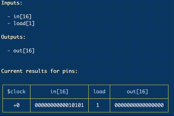
When the --run (-r) command is passed, it is possible to analyze how the pin values change in time (especially for the clocked gates). This options work with both, --exec-on-data (-e), and --describe (-d).
Here's an example running the Register truth table:
./bin/hdl-js --gate Register --describe --run
Which executes the gate in time:
Gate events
All gates emit events, which correspond to their internal logic handlers:
eval-- an event happening on evaluation of the compositional logicclockUp(value)-- an event happening, when a gate handled the clock's rising edge (aka "tick")clockDown(value)-- an event happening, when a gate handled the clock's falling edge (aka "tock")
Here's an example, how an external observer may subscribe to gate logic events:
const hdl = require('.');

const {
  emulator: {
    BuiltInGates: {
      Register,
    },
    Clock: {
      SystemClock,
    },
  },
} = hdl;

const r1 = Register.defaultFromSpec();

// Handle the event, when `r1` gets its output value:

r1.on('clockDown', () => {
  console.log(`r1 = ${r1.getPin('out').getValue()}`); // 255
});

// Setup the `r1` inputs, on the falling edge (clockDown)
// the value is set to the `out` pin:

r1.setPinValues({
  in: 255,
  load: true,
});

// Run the full clock cycle:

SystemClock
  .reset()
  .cycle();
NOTE: as described in Pins section, it is also possible to subscribe to
'change'event of individual pins.
Main chip groups
All gates are grouped into the following categories:
Very basic chips
This group includes two gates which can be used to build anything else.
For example, as was shown above, the basic And chip can be built on top of two connected Nand gates:
CHIP And {
  IN a, b;
  OUT out;

  PARTS:

  Nand(a=a, b=b, out=n);
  Nand(a=n, b=n, out=out);
}
Basic chips
The basic group of chips includes primitive building blocks for more complex chips. The basic chips themselves are built from the very basic chips. The group includes:
- And
- And16
- Or
- Or16
- Or8Way
- Nor16Way
- Not
- Not16
- Xor
- Mux (multiplexer)
- Mux16
- Mux4Way16
- Mux8Way16
- DMux (demultiplexer)
- DMux4Way
- DMux8Way
For example, the more complex HalfAdder chip can be built on top of Xor, and And gates:
CHIP HalfAdder {
  IN a, b;    // 1-bit inputs
  OUT sum,    // Right bit of a + b
      carry;  // Left bit of a + b

  PARTS:

  Xor(a=a, b=b, out=sum);
  And(a=a, b=b, out=carry);
}
The Mux (multiplexer) gate, which provides basic selection (or "if" operation), and being a basic chip, can itself be built from other basic chips from this group, such as Not, And, and Or.
To see the full specification and truth table of a needed gate, use --describe (-d) option from CLI.
ALU
The arithmetic-logic unit is an abstraction which encapsulates inside several operations, implemented as smaller sub-chips. Usually ALU accepts two numbers, and based on the OpCode (operation code), evaluates needed result. This group of chips includes:
The ALU chip itself evaluates both, arithmetic (such as addition), and logic (such as And, Or, etc) operations.
Memory chips
The basic building block for memory chips is a Flip-Flop. In particular, in this specific case, it's the DFF (Data/Delay Flip-Flop).
On top of DFF other storage chips, such as 1 Bit abstraction, or 16-bit Register abstraction, are built. The group includes the following chips:
- DFF (Data/Delay Flip-Flop)
- Bit (1-bit memory unit)
- Register (16-bit memory unit)
- ARegister (Address Register)
- DRegister (Data Register)
- PC (Program Counter)
- RAM (Random Access Memory)
- RAM8
- RAM64
- RAM512
- RAM4K
- RAM16K
Memory chips are synchronized by the clock, and operate on rising and falling edges of the clock cycle. Specification, and truth table of such chips contains $clock information, where negative values (e.g. -0) mean low logical level, and positive (+0) -- high logical level, or the rising edge.
The internal state of a clocked chip can only change on the rising edge. While the output is committed (usually to reflect the internal state) on the falling edge of the clock. This delay of the output is exactly reflected in the DFF, that is Delay Flip-Flop, name.
See detailed clock description in the next section.
Interface chips
The interface chips include the gates, which allow communicating to user input and output. These are:
Screen
The Screen chip represents 256 x 512 video memory, implemented with 8K registers. The gate can manipulate individual pixels using getPixelAt, and setPixelAt methods.
...

const screen = Screen
  .defaultFromSpec()
  .clear();

console.log(screen.getPixelAt(1, 16)); // 0

screen.setPixelAt(/* row */ 1,  /* column */ 16, 1);

console.log(screen.getPixelAt(1, 16)); // 1
Keyboard
The Keyboard chip is special, and requires callers to implement the actual keyboard listener, depending on a system where the chip is used. Such caller listeners should call Keyboard.emit('key', key) event, and the key code is propagated to the output pin:
Example using from a browser environment:
...

const keyboard = Keyboard.defaultFromSpec();

keyboard.getPin('out').on('change', value => {
  console.log('Char code: ' + value);
});

document.body.addEventListener('keypress', event => {
  Keyboard.emit('key', event.key);
});
The Keyboard also provides default (blocking) listen method, which spawns Node's stdin keyboard listening:
...

const keyboard = Keyboard.defaultFromSpec();

keyboard.getPin('out').on('change', value => {
  console.log('Char code: ' + value);
});

// Listen to stdin.
keyboard.listen();
We can introspect keyboard events using --describe option of the Keyboard gate:
hdl-js --gate Keyboard --describe
Result:
BuiltIn "Keyboard" gate:

Description:

  A keyboard, implemented as a 16 bit register that stores
  the currently pressed key code.

Inputs:

    Keyboard input

Outputs:

  - out[16]

Truth table: press any key...

┌──────┬─────┐
│ char │ out │
├──────┼─────┤
│  A   │ 65  │
└──────┴─────┘

Ctrl-c to exit...
Clock
The System clock is used to synchronize clocked chips (see example above in memory chips).
A clock operates on the clock rate, that is, number of cycles per second, measured in Hz. The higher the clock rate, the faster machine is.
Clock's runtime consists of cycles, and clock cycle has two phases: rising edge (aka "tick"), and falling edge (aka "tock").
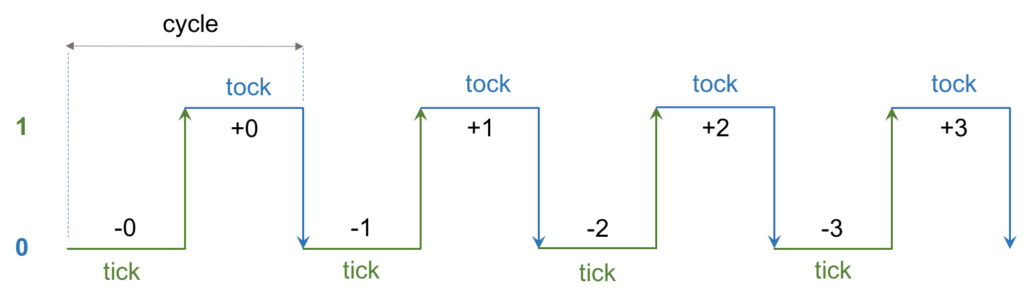
As mentioned in the memory chips section, all clocked gates can change their internal state only on the rising edge. And on the falling edge they commit the value form the state to the output pins.
For example, running the:
hdl-js --gate Bit --describe
Shows the clock information:
"Bit" gate:

Description:

  1 bit memory register.

  If load[t]=1 then out[t+1] = in[t] else out does not change.

  Clock rising edge updates internal state from the input,
  if the `load` is set; otherwise, preserves the state.

    ↗ : state = load ? in : state

  Clock falling edge propagates the internal state to the output:

    ↘ : out = state

Inputs:

  - in
  - load

Outputs:

  - out

Truth table:

┌────────┬────┬──────┬─────┐
│ $clock │ in │ load │ out │
├────────┼────┼──────┼─────┤
│   -0   │ 0  │  0   │  0  │
├────────┼────┼──────┼─────┤
│   +0   │ 1  │  1   │  0  │
├────────┼────┼──────┼─────┤
│   -1   │ 1  │  0   │  1  │
├────────┼────┼──────┼─────┤
│   +1   │ 1  │  0   │  1  │
├────────┼────┼──────┼─────┤
│   -2   │ 1  │  0   │  1  │
├────────┼────┼──────┼─────┤
│   +2   │ 0  │  1   │  1  │
├────────┼────┼──────┼─────┤
│   -3   │ 0  │  0   │  0  │
└────────┴────┴──────┴─────┘
From Node the Clock is available on the emulator object, and we can also get access to the global singleton SystemClock, which is used to synchronize the clocked chips:
const hdl = require('hdl-js');

const {
  emulator: {
    Clock,
    Pin,
  },
} = hdl;

const clock = new Clock({rate: 10, value: -5});
const pin = new Pin({name: 'a'});

// Track clock events.
clock.on('tick', value => pin.setValue(value));

clock.tick();

console.log(pin.getValue()); // +5;
Clock events
The clock emits the following events:
tick- rising edgetock- falling edgenext- half cycle (tickortock)cycle- full cycle (tick->tock)change- clock value change
All the clocked gates are automatically subscribed to SystemClock events, and update the value of their $clock pin:
const hdl = require('hdl-js');

const {
  emulator: {
    Gate,
    Clock: {
      SystemClock,
    },
  },
} = hdl;

class MyGate extends Gate {
  static isClocked() {
    return true;
  }

  eval() {
    // Noop, handle only clock signal.
    return;
  }

  clockUp(clockValue) {
    console.log('Handle rising edge:', clockValue);
  }

  clockDown(clockValue) {
    console.log('Handle falling edge:', clockValue);
  }
}

MyGate.Spec = {
  inputPins: ['a'],
  outputPins: ['b'],
};

const gate = MyGate.defaultFromSpec();

// Run full clock cycle.
SystemClock.cycle();

/*

Output:

Handle rising edge: 0
Handle falling edge: -1

*/
It is also possible to start, stop, and reset the clock:
const hdl = require('hdl-js');

const {
  emulator: {
    Clock: {
      SystemClock,
    },
  },
} = hdl;

// Reset the clock:
SystemClock.reset();

// Subscribe to the events:

SystemClock.on('tick', value => console.log('tick:', value));
SystemClock.on('tock', value => console.log('tock:', value));

// Run it:
SystemClock.start();

/*

Output (every second):

tick: +0
tock: -1
tick: +1
tock: -2
tick: +2
tock: -3
...

*/
Clock rate
The --clock-rate parameter controls the rate of the System clock. For example, the second run executes operations faster:
With default clock rate 1:
./bin/hdl-js --gate Register --describe --run
With clock rate 3:
./bin/hdl-js --gate Register --describe --run --clock-rate 3
Composite gates
The composite gates are created from other, more primitive, gates. By connecting inputs and outputs of the internal chips, it is possible to build an abstraction in a view of a resulting component, which encapsulates inside details of smaller sub-parts.
Although it is possible to create a composite gate manually using CompositeGate class from emulator, usually they are created via HDL.
Building chips in HDL
We already discussed briefly format of the HDL, and here we show how to create custom chips, building them from smaller blocks.
As mentioned, two very basic gates, the Nand, and Nor, can be used to build everything else in the computer chips.
In the example below, we use the Nand gate to implement a custom version of the And gate (even though the built-in And gate implementation exists):
// File: examples/And.hdl

CHIP And {
  IN a, b;
  OUT out;

  PARTS:

  Nand(a=a, b=b, out=n);
  Nand(a=n, b=n, out=out);
}
Here we connect two Nand gates in needed order, patching the output of the first one (via the internal pin n) to the inputs of the second Nand gate.
From a user perspective, the interface of our And gate looks as follows:
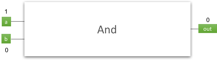
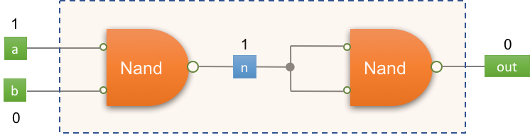
While if we look under the hood of the And gate implementation, we'll see the following picture:
NOTE: as in other systems, in hardware chips there might be multiple implementations for the same interface. E.g. we could build the
Andchip usingNorgates, instead ofNand.
So how does it work? The Nand stands for "negative-And" (or "not-And"). And first we feed our own a and b inputs to the first internal Nand chip, and get the "nand-result", saving it to the temporary (internal) pin n:
Nand(a=a, b=b, out=n);
As you can see, the Nand itself defines its inputs as a, and b, and output as out, which is propagated to our internal n.
NOTE: run
hdl-js --gate Nand --describeto see its specification.
Then, if to feed the same value to Nand chip, we get the "Not" operation -- and that exactly what we do in the second Nand "call", feeding the value of n to both, a, and b inputs:
Nand(a=n, b=n, out=out);
The resulting out from the second Nand is fed further to our own out pin. Eventually we got "not-not-And", and what is just "And":
Not(Nand(a, b)) == And(a, b)
NOTE: you can also get more details on the implementation in the wonderful nand2tetris course by Noam Nisan and Shimon Schocken.
Viewing composite gate specification
Getting a specification of a composite gate from HDL doesn't differ from getting the specification of a built-in chip, since the --gate option handles both gate types.
For example, to view the specification of our custom And gate from above (see also examples/And.hdl), we can just use the same --describe (-d) option:
hdl-js --gate examples/And.hdl --describe
What results to:
Custom "And" gate:

Description:

  Compiled from HDL composite Gate class "And".

Inputs:

  - a
  - b

Internal pins:

  - n

Outputs:

  - out

Truth table:

┌───┬───┬───┬─────┐
│ a │ b │ n │ out │
├───┼───┼───┼─────┤
│ 0 │ 0 │ 1 │  0  │
├───┼───┼───┼─────┤
│ 0 │ 1 │ 1 │  0  │
├───┼───┼───┼─────┤
│ 1 │ 0 │ 1 │  0  │
├───┼───┼───┼─────┤
│ 1 │ 1 │ 0 │  1  │
└───┴───┴───┴─────┘
As we can see, it correctly determined our internal pin n, and even showed it in the generated truth table.
NOTE: for 1-bit values the generated truth table shows all values. For larger pins, e.g. with size 16, a table with 5 random rows is shown. Try running the
hdl-js -g examples/Not16.hdl -d.
The truth table allows us also to check, whether our implementation in the PARTS section is correct (and it really is in this case!).
As an alternative, check also the specification of the built-in And gate -- you'll notice that it doesn't differ much, resulting to the same truth table for inputs and outputs.
And of course it is possible to do a sequential run of a custom gate too:
hdl-js --gate examples/Not16.hdl --describe --run
Using custom and built-in gates in implementation
In the example above, we used built-in native Nand gate to implement our own version of the And gate. However, once you have implemented some custom gate, you are free to use it further as a building block for even more abstracted chips.
For example, if we look at the examples/Mux.hdl file:
/**
 * Multiplexor:
 * out = a if sel == 0
 *       b otherwise
 */

CHIP Mux {
  IN a, b, sel;
  OUT out;

  PARTS:

  Not(in=sel, out=nel);
  And(a=a, b=nel, out=A);
  And(a=b, b=sel, out=B);
  Or(a=A, b=B, out=out);
}
Assuming the Mux.hdl file is in the same directory as the And.hdl, the And gate in the implementation is loaded exactly from our local custom implementation. Whereas, the Not, and Or are loaded from the built-ins. If we remove And.hdl from this directory, it will also be loaded from built-ins then.
Sometimes you may need to override local HDL-implementation, and use an explicit built-in gate in your call. For this we can use BUILTIN directive, which specifies that a particular chip call (or the whole gate definition) should be loaded from a corresponding built-in gate.
Example of providing the full backend for this chip:
Chip And {
  IN a, b;
  OUT out;

  // Delegate fully implementation of this chip
  // to the built-in `And` chip.
  BUILTIN And;
}
Example of overriding just some parts:
Chip Nand {
  IN a, b;
  OUT out;

  PARTS:

  And(a=a, b=b, out=a_and_b);
  Not(in=a_and_b, out=out);

  BUILTIN And;
}
In the example above the And gate in the implementation explicitly marked as a built-in, whereas the Not gate will be loaded from local HDL (if it exists). This might be very useful at debugging, when you need to exclude potential issues in you local version of And gate, and fall-back to the built-in version. Once you have successfully debugged the problem, you can restore loading And from local HDL version.
Loading HDL chips from Node
In Node it is possible to load a composite HDL gate class using the HDLClassFactory module, which is exposed on the emulator. The hdl-js itself also exposes two convenient wrappers: fromHDLFile, and fromHDL:
const hdl = require('hdl-js');

// Load `And` class from HDL:
const And = hdl.fromHDLFile('./examples/And.hdl');

// Instance of the class:
const and = And.defaultFromSpec();

// Test:
and
  .setPinValues({a: 1, b: 1})
  .eval();

// {a: 1, b: 1, n: 0, out: 1}
console.log(and.getPinValues());
Code generator
The code generator module allows exporting to HDL files from gate structures in other forms: from AST, from a composite gate instance, etc.
In general case it's an inverse procedure to parsing. In the simplest case you have a parsed AST, and the code generator can build an HDL code from it.
Exporting from AST
Having an AST of a gate, it is possible to generate an HDL code for it using the generator module. It is also possible to do some manipulations and transformations on this AST prior the generation:
const {
  parser,
  generator,
} = require('hdl-js');

const originalHDL = `
  CHIP And {
    IN a, b;
    OUT out;

    PARTS:

    Nand(a=a, b=b, out=n);
    Nand(a=n, b=n, out=out);
  }
`;

// Obtain the AST.
const ast = parser.parse(originalHDL);

// Slightly transform, reimplementing the second
// part as direct `Not` instead of `Nand`:

const {parts} = ast;

// Not(in=n, out=out);
parts[1] = {
  type: 'ChipCall',
  name: 'Not',
  arguments: [
    // First argument: `in=n`
    {
      type: 'Argument',
      name: {type: 'Name', value: 'in'},
      value: {type: 'Name', value: 'n'},
    },
    // Take second argument from the original call: `out=out`
    parts[1].arguments[2],
  ],
};

// Finally, generate the HDL code:

const exportedHDL = generator.fromAST(ast);

console.log(exportedHDL);

/*

Result:

CHIP And {
  IN a, b;
  OUT out;

  PARTS:

  Nand(a=a, b=b, out=n);
  Not(in=n, out=out);
}

*/
Exporting from Composite Gates
Composite gates are usually created in the declarative style using HDL syntax. Alternatively, one may need to create a composite gate directly in the imperative style, i.e. manually creating pins, connecting them together, etc.
In the example below we manually create a composite gate, and export it to HDL file:
NOTE: the preferred way of creating composite gates is still using declarative HDL notation. Use manual imperative style only in unusual programmatic cases.
const hdl = require('hdl-js');

const {
  generator,
  emulator: {
    CompositeGate,
    Pin,
    BuiltInGates: {
      And,
      Not,
    },
  },
} = hdl;

/*

We create manually (imperatively) a composite gate, corresponding
to the following declarative definition in HDL:

CHIP MyGate {
  IN x[16], y[16];
  OUT out[16];

  PARTS:

  And(a=x[0], b=y[0], out=temp);
  Not(in=temp, out=out[1]);
}

*/

// Inputs:
const x = new Pin({name: 'x', size: 16});
const y = new Pin({name: 'y', size: 16});

// Outputs:
const out = new Pin({name: 'out', size: 16});

// Internal pins:
const temp = new Pin({name: 'temp'});

// Parts:
const and = And.defaultFromSpec();
const not = Not.defaultFromSpec();

// Now connect needed pins to each other,
// creating a connection graph:

// ----------------------------------
// And(a=x[0], b=y[0], out=temp);

// a=x[0]
x.connectTo(and.getPin('a'), {
  sourceSpec: {index: 0},
});

// b=y[0]
y.connectTo(and.getPin('b'), {
  sourceSpec: {index: 0},
});

// out=temp
and.getPin('out').connectTo(temp);

// ----------------------------------
// Not(in=temp, out=out[1]);

// in=temp
temp.connectTo(not.getPin('in'));

// out=out[1]
not.getPin('out').connectTo(out, {
  destinationSpec: {index: 1},
});

// Create our gate instance:
const myGate = new CompositeGate({
  name: 'myGate',
  inputPins: [x, y],
  outputPins: [out],
  internalPins: [temp],
  parts: [and, not],
});

// Finally, export this composite gate to an AST
// structure, and generate HDL code:

const hdlCode = generator.fromCompositeGate(myGate);

console.log(hdlCode);

/*

Result:

CHIP MyGate {
  IN x[16], y[16];
  OUT out[16];

  PARTS:

  And(a=x[0], b=y[0], out=temp);
  Not(in=temp, out=out[1]);
}

*/